
A) RELIABILITY
Reliability, in system protection parlance, has special definitions which differ from the usual planning or operating usage. A relay can miss-operate in two ways: it can fail to operate when it is required to do so, or it can operate when it is not required or desirable for it to do so. To cover both situations, there are two components in defining reliability:DEPENDABILITY: This refers to the certainty that a relay will respond correctly for all faults for which it is designed and applied to operate; and
SECURITY: This is the measure that a relay will not operate incorrectly for any fault.
Most relays and relay schemes are designed to be dependable since the system itself is robust enough to withstand an incorrect trip-out (loss of security), whereas a failure to trip (loss of dependability) may be catastrophic in terms of system performance.
B) ZONES OF PROTECTION
The property of security is defined in terms of regions of a power system, called zones of protection, for which a given relay or protective system is responsible. The relay will be considered secure if it responds only to faults within its zone of protection. Figure 9.26 shows typical zones of protection with transmission lines, buses, and transformers, each residing in its own zone. Also shown are “closed zones” in which all power apparatus entering the zone is monitored, and “open” zones, the limit of which varies with the fault current. Closed zones are also known as “differential,” “unit,” or absolutely selective,” and open zones are “non-unit,” “unrestricted,” or “relatively selective.” |
| FIGURE 9.26 Closed and open zones of protection. |
The zone of protection is bounded by the current transformers (CT) which provide the input to the relays. While a CT provides the ability to detect a fault within its zone, the circuit breaker (CB) provides the ability to isolate the fault by disconnecting all of the power equipment inside its zone. When a CT is part of the CB, it becomes a natural zone boundary. When the CT is not an integral part of the CB, special attention must be paid to the fault detection and fault interruption logic. The CTs still define the zone of protection, but a communication channel must be used to implement the tripping function.
Although the operating time of relays often varies between wide limits, relays are generally classified by their speed of operation as follows:
1. INSTANTANEOUS: These relays operate as soon as a secure decision is made. No intentional time delay is introduced to slow down the relay response.
2. TIME-DELAY: An intentional time delay is inserted between the relay decision time and the initiation of the trip action.
3. HIGH-SPEED: A relay that operates in less than a specified time. The specified time in present practice is 50 milliseconds (3 cycles on a 60Hz system).
4.ULTRA HIGH-SPEED: This term is not included in the Relay Standards but is commonly considered to be operation in 4 milliseconds or less.
It is not always practical to duplicate every element of the protection chain. On High Voltage (HV) and EHV systems, the costs of transducers and circuit breakers are very expensive and the cost of duplicate equipment may not be justified. On lower voltage systems, even the relays themselves may not be duplicated. In such situations, a backup set of relays will be used. Backup relays are slower than the primary relays and may remove more of the system elements than is necessary to clear the fault.
REMOTE BACKUP: These relays are located in a separate location and are completely independent of the relays, transducers, batteries, and circuit breakers that they are backing up. There are no common failures that can affect both sets of relays. However, complex system configurations may significantly affect the ability of a remote relay to “see” all faults for which backup is desired. In addition, remote backup may remove more sources of the system than can be allowed.
LOCAL BACKUP: These relays do not suffer from the same difficulties as remote backup, but they are installed in the same substation and use some of the same elements as the primary protection. They may then fail to operate for the same reasons as the primary protection.
Automatic reclosing can be high speed or delayed. High Speed Reclosing (HSR) allows only enough time for the arc products of a fault to dissipate; generally 15–40 cycles on a 60 Hz base, whereas time delayed re-closings have a specific coordinating time, usually 1 or more seconds. HSR has the possibility of generator shaft torque damage and should be closely examined before applying it.
It is common practice in the U.S. to trip all three phases for all faults and then reclose the three phases simultaneously. In Europe, however, for single line-to-ground faults, it is not uncommon to trip only the faulted phase and then reclose that phase. This practice has some applications in the U.S., but only in rare situations. When one phase of a three-phase system is opened in response to a single phase-to-ground fault, the voltage and current in the two healthy phases tend to maintain the fault arc after the faulted phase is de-energized. Depending on the length of the line, load current, and operating voltage, compensating reactors may be required to extinguish this “secondary arc.”
OPERATING VOLTAGES: Transmission lines will be those lines operating at 138 kV and above, sub-transmission lines are 34.5 kV to 138 kV, and distribution lines are below 34.5 kV. These are not rigid definitions and are only used to generically identify a transmission system and connote the type of protection usually provided. The higher voltage systems would normally be expected to have more complex, hence more expensive, relay systems. This is so because higher voltages have more expensive equipment associated with them and one would expect that this voltage class is more important to the security of the power system. The higher relay costs, therefore, are more easily justified.
LINE LENGTH: The length of a line has a direct effect on the type of protection, the relays applied, and the settings. It is helpful to categorize the line length as “short,” “medium,” or “long” as this helps establish the general relaying applications although the definition of “short,” “medium,” and “long” is not precise. A short line is one in which the ratio of the source to the line impedance (SIR) is large (>4 e.g.), the SIR of a long line is 0.5 or less and a medium line’s SIR is between 4 and 0.5. It must be noted, however, that the per-unit impedance of a line varies more with the nominal voltage of the line than with its physical length or impedance. So a “short” line at one voltage level may be a “medium” or “long” line at another.
MULTI-TERMINAL LINES: Occasionally, transmission lines may be tapped to provide intermediate connections to additional sources without the expense of a circuit breaker or other switching device.
Such a configuration is known as a multi-terminal line and, although it is an inexpensive measure for strengthening the power system, it presents special problems for the protection engineer. The difficulty arises from the fact that a relay receives its input from the local transducers, i.e., the current and voltage at the relay location. Referring to Fig. 9.27, the current contribution to a fault from the intermediate source is not monitored. The total fault current is the sum of the local current plus the contribution from the intermediate source, and the voltage at the relay location is the sum of the two voltage drops, one of which is the product of the unmonitored current and the associated line impedance.
C) RELAY SPEED
It is, of course, desirable to remove a fault from the power system as quickly as possible. However, the relay must make its decision based upon voltage and current waveforms, which are severely distorted due to transient phenomena that follow the occurrence of a fault. The relay must separate the meaningful and significant information contained in these waveforms upon which a secure relaying decision must be based. These considerations demand that the relay take a certain amount of time to arrive at a decision with the necessary degree of certainty. The relationship between the relay response time and its degree of certainty is an inverse one and is one of the most basic properties of all protection systems.Although the operating time of relays often varies between wide limits, relays are generally classified by their speed of operation as follows:
1. INSTANTANEOUS: These relays operate as soon as a secure decision is made. No intentional time delay is introduced to slow down the relay response.
2. TIME-DELAY: An intentional time delay is inserted between the relay decision time and the initiation of the trip action.
3. HIGH-SPEED: A relay that operates in less than a specified time. The specified time in present practice is 50 milliseconds (3 cycles on a 60Hz system).
4.ULTRA HIGH-SPEED: This term is not included in the Relay Standards but is commonly considered to be operation in 4 milliseconds or less.
D) PRIMARY AND BACKUP PROTECTION
The main protection system for a given zone of protection is called the primary protection system. It operates in the fastest time possible and removes the least amount of equipment from service. On Extra High Voltage (EHV) systems, i.e., 345kV and above, it is common to use duplicate primary protection systems in case a component in one primary protection chain fails to operate. This duplication is therefore intended to cover the failure of the relays themselves. One may use relays from a different manufacturer, or relays based on a different principle of operation to avoid common-mode failures. The operating time and the tripping logic of both the primary and its duplicate system are the same.It is not always practical to duplicate every element of the protection chain. On High Voltage (HV) and EHV systems, the costs of transducers and circuit breakers are very expensive and the cost of duplicate equipment may not be justified. On lower voltage systems, even the relays themselves may not be duplicated. In such situations, a backup set of relays will be used. Backup relays are slower than the primary relays and may remove more of the system elements than is necessary to clear the fault.
REMOTE BACKUP: These relays are located in a separate location and are completely independent of the relays, transducers, batteries, and circuit breakers that they are backing up. There are no common failures that can affect both sets of relays. However, complex system configurations may significantly affect the ability of a remote relay to “see” all faults for which backup is desired. In addition, remote backup may remove more sources of the system than can be allowed.
LOCAL BACKUP: These relays do not suffer from the same difficulties as remote backup, but they are installed in the same substation and use some of the same elements as the primary protection. They may then fail to operate for the same reasons as the primary protection.
E) RECLOSING
Automatic reclosing infers no manual intervention but probably requires specific interlocking such as a full or check synchronizing, voltage or switching device checks, or other safety or operating constraints.Automatic reclosing can be high speed or delayed. High Speed Reclosing (HSR) allows only enough time for the arc products of a fault to dissipate; generally 15–40 cycles on a 60 Hz base, whereas time delayed re-closings have a specific coordinating time, usually 1 or more seconds. HSR has the possibility of generator shaft torque damage and should be closely examined before applying it.
It is common practice in the U.S. to trip all three phases for all faults and then reclose the three phases simultaneously. In Europe, however, for single line-to-ground faults, it is not uncommon to trip only the faulted phase and then reclose that phase. This practice has some applications in the U.S., but only in rare situations. When one phase of a three-phase system is opened in response to a single phase-to-ground fault, the voltage and current in the two healthy phases tend to maintain the fault arc after the faulted phase is de-energized. Depending on the length of the line, load current, and operating voltage, compensating reactors may be required to extinguish this “secondary arc.”
F) SYSTEM CONFIGURATION
Although the fundamentals of transmission line protection apply in almost all system configurations, there are different applications that are more or less dependent upon specific situations.OPERATING VOLTAGES: Transmission lines will be those lines operating at 138 kV and above, sub-transmission lines are 34.5 kV to 138 kV, and distribution lines are below 34.5 kV. These are not rigid definitions and are only used to generically identify a transmission system and connote the type of protection usually provided. The higher voltage systems would normally be expected to have more complex, hence more expensive, relay systems. This is so because higher voltages have more expensive equipment associated with them and one would expect that this voltage class is more important to the security of the power system. The higher relay costs, therefore, are more easily justified.
LINE LENGTH: The length of a line has a direct effect on the type of protection, the relays applied, and the settings. It is helpful to categorize the line length as “short,” “medium,” or “long” as this helps establish the general relaying applications although the definition of “short,” “medium,” and “long” is not precise. A short line is one in which the ratio of the source to the line impedance (SIR) is large (>4 e.g.), the SIR of a long line is 0.5 or less and a medium line’s SIR is between 4 and 0.5. It must be noted, however, that the per-unit impedance of a line varies more with the nominal voltage of the line than with its physical length or impedance. So a “short” line at one voltage level may be a “medium” or “long” line at another.
MULTI-TERMINAL LINES: Occasionally, transmission lines may be tapped to provide intermediate connections to additional sources without the expense of a circuit breaker or other switching device.
Such a configuration is known as a multi-terminal line and, although it is an inexpensive measure for strengthening the power system, it presents special problems for the protection engineer. The difficulty arises from the fact that a relay receives its input from the local transducers, i.e., the current and voltage at the relay location. Referring to Fig. 9.27, the current contribution to a fault from the intermediate source is not monitored. The total fault current is the sum of the local current plus the contribution from the intermediate source, and the voltage at the relay location is the sum of the two voltage drops, one of which is the product of the unmonitored current and the associated line impedance.
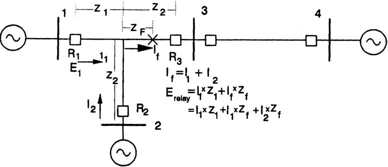 |
| FIGURE 9.27 Effect of infeed on local relays. |